Choosing a hydraulic flow control valve is not a simple catalog exercise. The correct choice depends on actuator speed, pressure, oil viscosity, temperature, and the required motion quality. A valve that performs well on a test bench may react differently beside a hot pump, long hose, or heavy cylinder.
Anthony Esposito, author of Fluid Power with Applications, states, “The function of a flow control valve is to control the rate of fluid flow.” That principle remains practical. A hydraulic flow control valve meters oil entering or leaving an actuator, which directly affects cylinder speed and motor rotation. Before selecting one, measure the actual flow rate. Check maximum working pressure. Consider whether the circuit needs pressure compensation, reverse free flow, or adjustable throttling. A needle valve may suit a simple, low-demand circuit. A pressure-compensated model offers steadier speed when load pressure changes.
Small details matter. A valve port that is too small can create heat and wasted energy. A valve rated far above the application may provide poor adjustment at low flow. That mistake is easy to overlook. I have also seen users select valves from nominal pipe size alone, then struggle with unstable cylinder movement. Size is not performance.
The best selection balances control, efficiency, serviceability, and cost. Confirm the manufacturer’s flow curves, sealing materials, contamination limits, and installation direction. Field conditions can expose weaknesses that specifications hide. Recheck the choice under real load, not only ideal laboratory conditions. A careful decision leaves room for uncertainty, because hydraulic systems rarely behave perfectly.
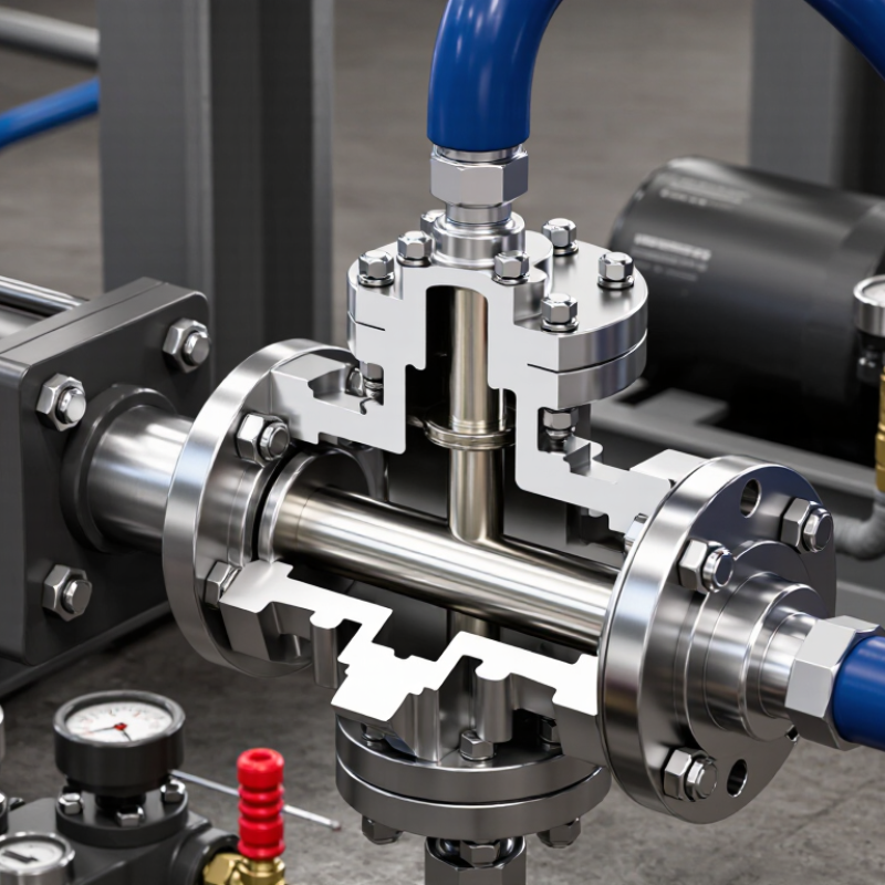
A hydraulic flow control valve regulates oil movement and controls actuator speed. In practical testing, flow adjustment changes cylinder movement more directly than pressure adjustment. Pressure mainly supplies the force needed to overcome resistance. Flow controls speed, but leakage and oil temperature can alter the result. Small changes matter. A valve should match the system’s rated flow, pressure, fluid viscosity, and operating temperature.
Common types serve different functions. Needle valves offer simple throttling, but their settings may change under varying loads. Pressure-compensated flow control valves maintain a steadier flow when pressure fluctuates. One-way flow control valves restrict flow in one direction and allow freer return movement. Flow dividers split incoming oil between circuits, although unequal loads can affect accuracy.
Meter-in control suits resisting loads, while meter-out control often prevents a cylinder from running ahead.
Installation details are easy to underestimate. I have seen unstable motion caused by contaminated oil, not a defective valve. Place the valve where technicians can adjust and inspect it safely. Check whether the actuator needs controlled extension, retraction, or both. A bypass check valve may improve reverse movement. Oversizing can make fine adjustment difficult, while undersizing creates heat and pressure loss. The right choice is not always the most precise model. Test the valve under realistic load conditions, then record temperature, speed, and pressure readings.
Before choosing a hydraulic flow control valve, measure the system as it actually operates. Record required flow, pressure, fluid temperature, viscosity, actuator speed, and load changes. A design pressure alone is not enough. During commissioning, pressure spikes often appear when cylinders stop suddenly or valves close too quickly. These moments can exceed the normal gauge reading.
Energy deserves equal attention. The European Commission’s energy-efficiency reference materials report that motor-driven systems can consume about 65% of industrial electricity. The U.S. Department of Energy also estimates that pumping systems use roughly 27% of industrial motor electricity. These figures are not specific to every hydraulic circuit, but they show why pressure loss matters. A valve with excessive throttling may control speed accurately while quietly increasing heat and operating cost.
Check contamination levels, filtration, duty cycle, installation space, and maintenance access before approval. ISO 4413:2010 requires hydraulic systems to address safety, pressure control, and foreseeable operating conditions. Field experience also shows that fluid cleanliness is frequently underestimated. A clean workshop does not guarantee clean oil. Review the actuator’s minimum stable speed, not only its maximum speed. Confirm the valve’s rated flow at the intended pressure drop, then test it under real load. A neat calculation can still mislead. Hose expansion, oil temperature, and changing loads may alter performance. That assumption needs challenge.
Choosing a hydraulic flow control valve starts with the required flow range, not the port size.
A valve rated for 60 L/min may behave poorly at 2 L/min. Check the manufacturer’s flow coefficient, pressure drop, and controllable range. The U.S. Department of Energy’s Pumping System Sourcebook reports that pumping systems can represent 25–50% of industrial electricity use. Excessive throttling can therefore increase operating costs and heat.
Pressure conditions need equal attention. Record normal pressure, peak pressure, and return-line pressure near the valve. ISO 4413 requires hydraulic systems to address safe pressure control and energy release.
A valve with a 210-bar rating may still fail if pressure spikes exceed that value repeatedly. Use a relief strategy that matches the circuit. Do not size from catalog maximums alone.
Fluid conditions often expose weak selections. Confirm viscosity at startup and operating temperature, then check seal compatibility with the actual fluid. ISO 11171 cleanliness codes help define contamination limits for hydraulic oil.
A dirty workshop can quickly turn a precise metering valve into a sticky component. I once selected a valve using nominal viscosity only; cold starts became slow and unstable. That choice looked correct on paper. It was not.
For proportional control, verify response time, hysteresis, and signal requirements under load.
For simple speed adjustment, a pressure-compensated valve may provide steadier actuator movement. Measure flow with a calibrated instrument after installation. Field readings matter more than assumptions.
How to Choose a Hydraulic Flow Control Valve
Installation method affects maintenance, stability, and response speed. Inline valves suit compact circuits and quick replacement. However, long hoses can increase pressure loss and delay actuator movement. Manifold or subplate mounting creates cleaner routing. It also reduces leakage points near the machine. Cartridge valves save space, but their cavities require accurate machining and careful contamination control. During commissioning, I check port orientation, access for adjustment, and whether technicians can remove the valve without draining the entire system.
Control features should match the working cycle. A basic needle valve can regulate flow economically, but load changes may alter actuator speed. Pressure-compensated models maintain steadier flow when resistance varies. Integrated check functions allow free return flow, which can improve cylinder retraction. Proportional control offers remote adjustment and smoother transitions. Yet, electrical resolution, signal filtering, and oil cleanliness can limit its real benefit. More features are not always better.
Response performance deserves a practical test. Apply a step change in command, then record flow, pressure, and actuator position. Fast response may reduce cycle time, but excessive sensitivity can cause hunting or sudden movement. I look for stable settling rather than the quickest first reaction. Temperature matters too. Cold oil may make the valve feel sluggish, while hot oil can increase leakage. A tidy installation can still perform poorly if the valve is oversized, the sensor is misplaced, or the control setting is rushed. One detail is often missed: verify performance under the actual load, not only on a test bench.
Representative comparison for a 25 L/min hydraulic circuit. Inline valves are compact and simple to adjust, subplate-mounted valves provide better pressure compensation, and cartridge valves typically offer the fastest response and lowest pressure loss when installed in a properly designed manifold.
How to Choose a Hydraulic Flow Control Valve
Compatibility should be checked before comparing price or delivery time. Confirm the working fluid, pressure range, temperature, port size, and expected flow rate. Mineral oil, water-based fluids, and biodegradable fluids can affect seals differently. A valve rated for pressure may still fail if its seals are chemically unsuitable. Check the manufacturer’s technical data, not only the product label.
Maintenance needs often decide whether a valve performs well in real equipment. Choose a design that allows inspection without removing nearby hoses. Install a clean filter upstream, because small particles can damage the metering edge. During routine service, inspect leaks, unusual noise, slow actuator movement, and unstable flow. Record pressure and temperature readings. Small changes can reveal wear early. I have seen maintenance plans fail because access was ignored during installation. That mistake is expensive to correct.
Operating safety requires more than selecting the correct pressure rating. Confirm that the valve will not create excessive back pressure or unexpected actuator movement. A pressure relief device may be necessary in the circuit. Protect operators from hot surfaces and escaping fluid. Before servicing, isolate the energy source and release stored pressure. Never rely on a closed valve alone. Test the system at low pressure after maintenance, then increase pressure gradually. Imperfect assumptions happen. Recheck them.
| Selection Dimension | What to Check | Practical Guidance | Typical Risk if Mismatched | Recommended Action |
|---|---|---|---|---|
| Flow Rate Range | Required minimum, normal, and maximum flow rate; flow units; expected variation during operation. | Select a valve whose rated flow range covers the full operating range. Avoid sizing only for the average flow. | Poor adjustment resolution, excessive pressure drop, unstable actuator speed, or restricted flow. | Compare the system flow requirement with the valve flow-versus-pressure-drop curve. |
| Pressure Rating | Maximum continuous pressure, peak pressure, shock loads, and return-line pressure. | The valve pressure rating must meet or exceed the highest pressure at its installation point, including transient spikes. | Seal damage, body deformation, leakage, or sudden component failure. | Verify working and peak pressure ratings against the machine’s relief-valve setting and measured peaks. |
| Valve Configuration | Need for fixed flow control, adjustable flow control, one-way flow control, or pressure-compensated flow control. | Use a one-way flow-control valve when free flow is needed in one direction and metered flow in the opposite direction. Use pressure compensation when load or pressure changes are significant. | Actuator speed changes with load, unwanted reverse restriction, or inability to meet cycle-time requirements. | Define the required flow direction and select the control principle before choosing port connections. |
| Port Size and Connection | Port thread or flange standard, nominal size, installation orientation, and available space. | Connection size alone does not determine capacity; confirm the valve’s rated flow and allowable pressure drop. | Incorrect fit, leakage, excessive turbulence, difficult installation, or premature thread damage. | Match the connection standard exactly and use compatible adapters only when approved for the pressure class. |
| Hydraulic Fluid Compatibility | Fluid type, viscosity range, temperature range, additives, and seal compatibility. | Mineral-oil systems and fire-resistant fluids may require different seal and body materials. Check the manufacturer’s fluid compatibility chart. | Swollen or hardened seals, internal corrosion, sticking, and external leakage. | Confirm material compatibility for the actual fluid and temperature before installation. |
| Operating Temperature | Minimum and maximum fluid temperature, ambient temperature, and heat generated by throttling. | Flow-control valves convert part of the hydraulic energy into heat. Pressure drop and flow should be evaluated together. | Viscosity changes, sluggish response, seal deterioration, or overheating of the circuit. | Check temperature limits and calculate whether the cooler and reservoir can dissipate added heat. |
| Filtration and Cleanliness | Required cleanliness level, filter location, filter condition, and risk of contamination during service. | Small metering clearances can be affected by particles. Clean fluid and clean installation practices are essential. | Spool sticking, erratic flow, blocked orifices, accelerated wear, and internal leakage. | Install suitable filtration, inspect filter indicators, and flush contaminated circuits before commissioning. |
| Adjustment and Control | Manual adjustment, tamper resistance, remote control, repeatability, and need for an electronic actuator. | Use a lockable adjustment where unauthorized changes could affect machine safety or cycle performance. | Unexpected speed changes, inconsistent cycles, or unsafe movement after adjustment. | Document the normal setting and secure the adjustment after commissioning. |
| Maintenance Access | Availability of replacement seals, cleaning access, inspection points, and space for removal. | A valve that can be isolated and serviced without removing major assemblies reduces downtime and maintenance risk. | Longer downtime, poor cleaning practices, and delayed replacement of worn components. | Provide isolation points, pressure test ports, and adequate clearance around the valve. |
| Leakage Control | Permitted external and internal leakage, seal material, fitting torque, and hose condition. | Internal leakage can increase actuator drift and reduce efficiency; external leakage creates safety and environmental hazards. | Loss of motion control, hot-fluid exposure, contamination, and slipping hazards. | Inspect connections regularly and replace damaged seals; never tighten fittings on a pressurized system. |
| Response and Stability | Load variation, actuator inertia, required speed stability, and potential for oscillation or vibration. | Pressure-compensated control generally provides more consistent flow when differential pressure varies, but system dynamics must still be checked. | Jerky motion, hunting, noise, vibration, or inaccurate positioning. | Test the valve under minimum and maximum expected loads, not only at no-load conditions. |
| Operating Safety | Stored pressure, unexpected actuator movement, load-holding requirements, guarding, and emergency procedures. | A flow-control valve is not automatically a load-holding or pressure-relief device. Separate safety functions may be required. | Uncontrolled descent, unexpected movement, injection injury, or damage to machinery. | Depressurize before service, block or support raised loads, and use relief and load-holding devices where required by the application. |
| Verification Before Start-Up | Correct flow direction, tightened connections, clean fluid, pressure-test results, and adjustment setting. | Start at low pressure and low speed where possible, then increase gradually while checking for leaks and abnormal noise. | Immediate leakage, unstable movement, component damage, or unsafe commissioning conditions. | Use a documented commissioning checklist and record final pressure, flow, temperature, and adjustment values. |