What Is a Flow Regulator and How Does It Work?
A flow regulator controls how much liquid or gas passes through a pipe over time. Picture a valve on a water line: turn its handle, and the stream narrows or opens. In automated equipment, sensors and actuators can adjust the setting without a person turning a knob. The aim is steady, usable flow—not simply maximum flow.
The U.S. Department of Energy’s Improving Pumping System Performance: A Sourcebook for Industry recommends assessing pumps as part of the full system. Pipe layout, pressure losses, and control choices all affect performance. That guidance matters because a regulator cannot correct every underlying problem. A clogged filter, undersized pipe, or poorly matched pump may still cause unstable flow. Small parts matter.
A flow regulator may work through a spring-loaded diaphragm, a pressure-compensating cartridge, or an electronically controlled valve. Each design responds differently to changing inlet pressure and operating conditions. For example, a regulator might keep a cooling-water line near its target rate while another machine starts nearby. In practice, the displayed setting is not always the delivered flow. Measurement, calibration, and regular inspection help verify it.
This article explains what flow regulators do, how common mechanisms respond to pressure, and where they are used. It also considers their limits. A regulator is one component, not a cure-all. Engineers should select one using the fluid, required flow range, pressure conditions, and manufacturer specifications. DOE’s sourcebook is a useful reference, but each installation still needs its own measurements. A neat diagram rarely shows the whole system.
Definition and Purpose of a Flow Regulator
A flow regulator is a device that controls how much fluid or gas passes through a system over time. Its purpose is to keep the flow rate within a desired range, such as a steady stream of water through a pipe or a measured supply of air to a tool. Flow is commonly expressed in units such as liters per minute.
Some regulators use a fixed opening, while adjustable models let an operator change the setting. Pressure-compensated designs can help maintain a more consistent flow when inlet pressure changes. They do not all work the same way. A basic restrictor may reduce flow, but its output can still shift as pressure or fluid conditions change.
That distinction matters. A flow regulator controls flow; a pressure regulator controls pressure. In a real installation, the right choice depends on the fluid, operating pressure, temperature, and required accuracy. Even a well-specified unit can behave differently if a filter becomes clogged or the fluid is more viscous than expected. It is worth checking the measured flow under actual operating conditions. Specifications help, but they are not the whole story.
Key Components and Their Functions
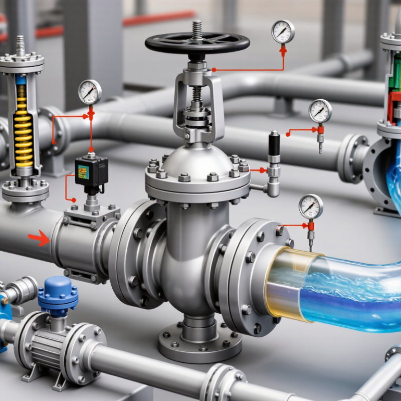
A flow regulator controls how much fluid passes through a pipe or device over time. Its main components sit inside a compact body with an inlet and an outlet. The body guides fluid through a narrow passage, while the passage shape helps set the available flow. Small parts matter. A needle or adjustable orifice changes the opening size when the user turns an adjustment knob. In a pressure-compensated design, a spring and diaphragm or piston respond to pressure changes and shift the opening to help keep flow steadier.
Seals prevent leaks around moving parts and connections. Their material must suit the fluid, temperature, and operating pressure. A clogged passage or worn seal can cause unstable readings, even when the regulator looks intact. Not always obvious. For example, a regulator on a water line may deliver less flow when debris collects at its inlet screen. Check the rated flow range and pressure limits before installation, then measure flow under actual operating conditions. A basic regulator does not necessarily hold flow constant across every pressure change; performance depends on its design and the system around it. Turning the knob too far can also restrict flow more than intended.
How a Flow Regulator Controls Flow
What Is a Flow Regulator and How Does It Work?
How a Flow Regulator Controls Flow
A flow regulator controls how much liquid or gas passes through a line during a set time. Inside, a valve or narrow opening creates resistance. Adjustable models let an operator change that opening; pressure-compensating models respond to pressure changes to help maintain a steadier flow. The exact mechanism varies by design.
Imagine water entering a small tube. If pressure rises, more water may rush through unless the regulator adjusts its passage. Some regulators use a spring-loaded diaphragm to sense pressure and move a valve. Others simply provide a fixed restriction, so flow can shift when inlet pressure changes. A regulator is not magic: the fluid, pressure range, and correct sizing all matter. In practice, readings can wander, especially when a system is dirty or operating outside its rated range. I’d check actual flow rather than assume the setting tells the whole story.
Tips: Install the regulator in the direction marked on its body, if shown. Use a flow meter to verify output, and inspect for clogged screens or leaks. Small details matter. A poorly matched regulator may restrict flow too much or fail to hold it steady.
Common Types of Flow Regulators
Common Types of Flow Regulators
Flow regulators control how much fluid or gas passes through a system over time. Needle valves are a common adjustable type. A tapered needle moves toward or away from a small opening, changing the flow path. Small turns matter. These valves work well for careful manual adjustments, such as setting water flow through a laboratory line. They may respond slowly, and readings can shift when pressure changes.
Fixed orifice regulators use a small, precisely sized opening to restrict flow. They are simple and have few moving parts, but their output depends on the pressure conditions around them. Pressure-compensating regulators use internal parts, such as a spring-loaded spool or diaphragm, to help keep flow steadier as pressure varies. The effect has limits. Electronic mass flow controllers add sensors and control valves, allowing more precise adjustments in suitable systems. In practice, product labels sometimes blur the difference between a flow regulator and a pressure regulator. Checking the rated flow range, fluid compatibility, and operating pressure is more useful than relying on the name alone.
Typical Applications Across Different Systems
A flow regulator keeps liquid or gas moving near a chosen rate, even when upstream pressure changes. In hydronic heating and cooling, it helps distribute water through separate loops. A small valve near a fan-coil unit can prevent one branch from taking excessive flow while another stays under-supplied. The U.S. Department of Energy’s Improving Pumping System Performance reports that pumping systems use about 20% of global electricity. That figure makes careful flow control relevant to energy management, though a regulator alone cannot guarantee savings. The pump, pipe layout, and control settings matter too.
In industrial process lines, regulators help maintain repeatable feed rates for cooling water, wash cycles, or dosing liquids. In irrigation, they can reduce pressure-driven differences between emitters, helping water reach plants more evenly across a field. Water-treatment systems also use flow regulation to keep filtration and chemical-treatment stages within operating ranges. Small changes matter. A partially clogged filter, for example, may alter pressure and upset the intended flow. Operators should check actual flow under working conditions, not rely only on a valve setting. That detail is easy to miss. The DOE report also notes that pumping can account for 25–50% of energy use in some industrial facilities, but site-specific measurement is needed before estimating any benefit.