


2026 How to Choose a Steam Pressure Reducing Valve?
Choosing a steam pressure reducing valve in 2026 requires more than matching inlet and outlet pressures. The valve must manage real steam conditions, including fluctuating demand, wet steam, temperature changes, and pressure surges. A model that performs well during commissioning may behave poorly when several production lines open simultaneously. That detail is easy to miss.
Richard E. Putnam, a respected steam-plant author and engineer, wrote, “Control pressure first; everything else depends on it.” This principle remains useful, although it is not a complete selection method. Engineers must also examine flow capacity, minimum operating pressure, valve authority, installation orientation, and maintenance access. The correct steam pressure reducing valve should protect downstream equipment while delivering stable pressure at the point of use.
Look closely at the plant floor.
A practical assessment begins with measured data, not assumptions. Record the inlet pressure, required outlet pressure, normal flow, peak flow, and acceptable pressure variation. Check whether the steam is dry enough for reliable control. Moisture can erode internal components and create unstable operation. A separator, strainer, safety valve, and suitable bypass may also be necessary, depending on the system design.
Some specifications remain incomplete. That is a problem. Many buyers focus on nominal pipe size and overlook turndown performance. Others select a valve from a catalog without checking noise, velocity, or shutoff behavior. This guide explains how to compare valve types, sizing methods, materials, control response, and lifecycle costs. It also considers common installation mistakes, because even an excellent valve cannot compensate for poor piping, inadequate drainage, or careless commissioning.
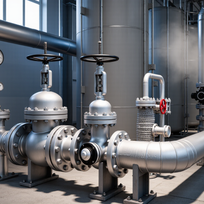
Steam Pressure Reducing Valve Basics and Operating Principles
A steam pressure reducing valve (PRV) lowers higher inlet pressure to a controlled downstream level. It protects equipment, improves heat transfer, and supports stable process conditions. Inside, a spring or pilot mechanism senses downstream pressure. When pressure drops, the valve opens. When pressure rises, it closes. Simple in theory. Steam flow makes it demanding. Temperature, velocity, and condensate can quickly expose weak sizing or poor installation.
A direct-acting valve uses outlet pressure against a diaphragm and spring. It suits smaller loads and moderate pressure changes. A pilot-operated valve uses a small control valve to regulate the main valve. This design responds more precisely across changing flow rates. The set pressure is not the inlet pressure. It is the pressure measured after the valve, usually through a downstream sensing line. That detail is often missed. A poorly placed sensor can create hunting, noise, and unstable pressure.
Choose the valve from pressure, temperature, steam capacity, turndown, and allowable pressure loss. Oversizing may cause frequent opening and closing, while undersizing restricts production. Install a strainer, isolation valves, gauges, and a suitable downstream safety device. Drain condensate before it reaches the PRV. Check the arrow, flow direction, and sensing connection. In field inspections, insulation and pipe support are easy to overlook. They matter. Commission slowly, adjust in small increments, and verify pressure under real load. Static readings can mislead. A valve that behaves well at no flow may respond poorly during morning startup.
2026 How to Choose a Steam Pressure Reducing Valve? – Steam Pressure Reducing Valve Basics and Operating Principles
Technical selection guide covering valve function, operating principles, sizing factors, installation requirements, and maintenance considerations.
| Category | Selection Dimension | Technical Data and Operating Principle | Practical Selection Guidance |
|---|---|---|---|
| Basic Function | Primary purpose | A steam pressure reducing valve lowers a higher upstream steam pressure to a controlled lower downstream pressure while allowing steam to flow automatically. | Use it when downstream equipment requires a stable pressure below the available plant or boiler pressure. |
| Operating Principle | Self-operated control | The downstream pressure acts through a sensing passage, diaphragm, or piston against an adjustment spring. The valve throttles open or closed to balance the set pressure. | Suitable for many general steam services where an external control signal is not required. |
| Operating Principle | Pilot-operated control | A small pilot valve controls pressure acting on the main valve diaphragm or piston. This design can provide tighter regulation over a wider flow range. | Consider for larger capacities, variable loads, or applications requiring improved pressure stability. |
| Pressure Conditions | Inlet pressure | The maximum and minimum upstream pressures affect valve trim loading, capacity, and controllability. Inlet pressure may vary during plant operation. | Specify the normal, minimum, maximum, and design inlet pressures rather than only one operating value. |
| Pressure Conditions | Outlet pressure | The outlet pressure is the controlled pressure delivered to the process. The setpoint must remain within the valve's rated adjustment range. | Select a valve whose recommended operating range includes the required downstream set pressure. |
| Pressure Conditions | Pressure differential | The available pressure drop is the difference between inlet and outlet pressure. Excessive or insufficient differential pressure can affect capacity and stability. | Check differential pressure at minimum and maximum flow conditions before final sizing. |
| Flow Sizing | Steam flow rate | Valve capacity is determined by required steam mass flow, inlet pressure, outlet pressure, steam temperature, and whether the flow is saturated or superheated. | Provide minimum, normal, and maximum steam consumption. Avoid sizing only from the average load. |
| Flow Sizing | Valve capacity margin | A moderate capacity margin allows for operating variation, but excessive oversizing can cause poor control, hunting, and premature seat wear. | Choose the smallest valve that safely handles the maximum required flow while maintaining stable control at normal flow. |
| Flow Sizing | Critical pressure ratio | When steam accelerates to sonic velocity through the restriction, increasing downstream pressure reduction may not increase mass flow proportionally. This condition is commonly associated with choked flow. | Use recognized steam-flow sizing methods and verify noise, velocity, and erosion limits when pressure reduction is large. |
| Steam Quality | Saturated steam | Saturated steam is at the temperature corresponding to its pressure. Excess moisture can reduce valve life and contribute to wire drawing, erosion, and unstable control. | Install effective upstream drainage and steam separation where wet steam may be present. |
| Steam Quality | Superheated steam | Superheated steam has a temperature above the saturation temperature at its pressure. Material temperature ratings and packing limits must account for the actual temperature. | Specify both pressure and temperature, not pressure alone, when selecting materials and seals. |
| Valve Construction | Body and trim materials | Common steam valve constructions use pressure-rated metallic bodies and erosion-resistant internal trim. Material selection depends on pressure, temperature, corrosion conditions, and applicable standards. | Confirm pressure-temperature ratings and material compatibility with the steam system and local codes. |
| Valve Construction | Diaphragm or piston assembly | The sensing element responds to downstream pressure and moves the valve plug. Diaphragm designs are generally responsive, while piston designs may be selected for higher force or demanding service. | Match the actuator construction to pressure range, temperature, cycling frequency, and maintenance requirements. |
| Control Performance | Pressure stability | Pressure stability depends on valve sizing, spring range, sensing arrangement, flow variation, piping layout, and the dynamic response of the valve. | For rapidly changing loads, evaluate response time, droop, and control accuracy in addition to nominal capacity. |
| Control Performance | Droop | Droop is the change in downstream pressure that occurs as flow changes. Some self-operated valves intentionally allow a small pressure change to maintain stable operation. | Select a design with acceptable droop for the process; critical users may require a pilot-operated or externally controlled arrangement. |
| Noise and Safety | Noise and vibration | High pressure drops and high steam velocities can generate aerodynamic noise and mechanical vibration. These effects may increase with undersized piping or excessive valve velocity. | Check allowable noise levels, downstream velocity, pipe supports, and the need for a low-noise trim or diffuser. |
| Safety | Overpressure protection | A pressure reducing valve is a regulating device and should not be treated as the sole protection against downstream overpressure. A suitable relief device may be required. | Review the failure mode and install downstream pressure relief protection where the reduced-pressure equipment cannot withstand upstream pressure. |
| Installation | Upstream strainer | A strainer helps remove pipe scale, rust, and debris that could damage the seat, plug, pilot, or sensing passages. | Install an appropriately rated strainer upstream and provide access for cleaning. |
| Installation | Steam separator and trap | A separator and correctly sized steam trap can remove entrained condensate. Condensate entering the valve may cause water hammer, erosion, and unstable regulation. | Provide drainage at low points and maintain a dry, clean steam supply to the reducing valve. |
| Installation | Pressure sensing location | The downstream sensing connection should be located where pressure is representative and sufficiently away from turbulence caused by the valve, elbow, or abrupt pipe transition. | Follow the valve installation instructions and avoid sensing pressure immediately at a turbulent fitting. |
| Installation | Isolation and bypass | Isolation valves allow inspection or replacement. A manual bypass may support startup or maintenance but can create a risk of uncontrolled downstream pressure if improperly operated. | Use a controlled startup procedure and ensure bypass operation cannot expose downstream equipment to unsafe pressure. |
| Maintenance | Inspection points | Pressure gauges upstream and downstream help identify blocked strainers, incorrect adjustment, valve wear, or changing supply conditions. | Install gauges with suitable ranges and isolation arrangements for safe testing and calibration. |
| Maintenance | Common fault: downstream pressure too high | Possible causes include a damaged seat, debris preventing closure, incorrect spring adjustment, pilot malfunction, or excessive sensing-line pressure loss. | Check the setpoint, sensing passage, strainer, pilot components, and valve seat before changing the spring setting. |
| Maintenance | Common fault: pressure hunting | Hunting may result from an oversized valve, rapid load changes, inadequate sensing-line placement, unstable inlet pressure, or condensate in the steam line. | Verify sizing, drainage, sensing geometry, and operating conditions before replacing the valve. |
| Selection Checklist | Required specification data | A complete inquiry should include steam type, minimum and maximum flow, inlet and outlet pressures, temperature, pipe size, connection standard, installation orientation, allowable noise, and safety requirements. | Use the complete operating envelope to obtain a technically appropriate valve rather than selecting by line size alone. |
Important: Final valve sizing, pressure-temperature verification, relief protection, and installation should be checked against applicable piping codes, safety regulations, and the equipment manufacturer's certified technical data.
Related Posts
-
How to Optimize Your System with Swagelok Back Pressure Regulators
-
Top 10 Back Pressure Valves Every Global Buyer Should Know?
-
Understanding Flow Regulators: Key Components for Optimizing Fluid Control Systems
-
What is a Pressure Reducing Valve and How Does It Ensure System Efficiency
-
What Are the Top 10 Pressure Valve Types in China?
-
Embracing Industry 2025 Innovations for the Ultimate Water Pressure Regulator Valve Solutions