What Are the Top Types of Hydrogen Pressure Regulators?

Hydrogen systems depend on accurate pressure control, from storage cylinders to fuel-cell inlets. A hydrogen pressure regulator reduces high supply pressure and helps keep downstream equipment within its operating range. The right choice affects flow stability, component life, and safe system performance. Small details matter: inlet pressure, outlet range, flow demand, gas purity, and seal compatibility can change which design fits.

Common options include single-stage and two-stage regulators, pressure-reducing valves, and specialized high-pressure or point-of-use models. Each addresses a different operating need. A two-stage unit can help maintain steadier outlet pressure as cylinder pressure falls, while a single-stage model may suit less variable applications. But no type is automatically best. Sizing, materials, connections, and installation conditions deserve equal attention. A regulator that looks suitable on a specification sheet may behave differently under real flow demand.

This guide compares the main types, their typical uses, and the practical trade-offs engineers should assess before selection. It also considers questions such as pressure stability, response, and maintenance access. One important limitation: no source material was provided for a verifiable quotation from a named hydrogen-regulator expert, so I cannot responsibly attribute a direct quote. A sound principle still applies: match the regulator to the system, not just the pressure rating.
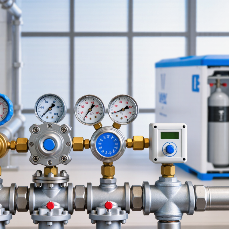
What Are the Top Types of Hydrogen Pressure Regulators?

Hydrogen Regulator Duty: SAE J2601 Covers 35 MPa and 70 MPa Fueling

What Are the Top Types of Hydrogen Pressure Regulators?

Hydrogen pressure regulators are commonly selected by inlet pressure, outlet range, flow capacity, and stage count. SAE J2601 adds an important duty context: it defines fueling protocols for 35 MPa and 70 MPa vehicle systems. These pressure classes are not interchangeable. During a fill, pressure, gas temperature, and delivery rate must stay within the applicable protocol. A regulator controls pressure; it does not make a complete fueling system compliant by itself. That distinction is easy to miss.

Tips: Check the regulator’s rated inlet pressure, hydrogen-compatible materials, seals, and flow performance. Consider changing temperatures and pressure during a rapid fill. Small details matter.

For either pressure class, compare regulator performance across the full operating range, not just at one steady test point. A unit may respond differently as inlet pressure drops or flow demand changes. Confirm suitability through documented testing and review by qualified engineers. A tidy specification table can hide real operating variation; selection is not always straightforward.

Single-Stage Regulators: One-Step Pressure Reduction for Steady Inlet Supply

A single-stage hydrogen pressure regulator reduces inlet pressure to a lower outlet pressure in one step. Its compact design can suit systems supplied from a relatively steady upstream source. For example, a technician may monitor the inlet gauge while setting the outlet to match the equipment’s specified operating range. Keep the adjustment gradual, and verify the reading after flow begins. Small changes can matter.

The main limitation is that outlet pressure may shift as inlet pressure changes, especially as a gas cylinder empties. That behavior is sometimes overlooked. A single-stage regulator may not hold the same outlet pressure across a wide inlet range, so check its pressure and flow specifications against actual operating conditions. Inspect compatible wetted materials, connections, and seals, and use leak-detection methods suitable for hydrogen. A qualified technician should confirm the installation and test for leaks before operation. The setup can be straightforward, but the pressure readings deserve a second look.

Two-Stage Regulators: Two-Step Control as Cylinder Pressure Falls

A two-stage hydrogen pressure regulator reduces cylinder pressure in two controlled steps. The first stage drops the high inlet pressure to an intermediate level. The second stage then controls delivery pressure to the process or instrument. This staged action can limit outlet-pressure changes as the cylinder empties. That matters. The U.S. Department of Energy’s Hydrogen Storage overview describes onboard storage systems operating at 350 or 700 bar, roughly 5,000 or 10,000 psi. At these pressures, a falling cylinder gauge reading can mean changing conditions at the regulator inlet.

In practice, the two stages share the work. The first responds to cylinder pressure; the second helps maintain a steadier downstream setting. This is useful where a stable flow supports repeatable measurements or process control. It is not magic. Flow demand, temperature, regulator sizing, and installation all affect performance, so pressure can still drift. A regulator selected for the wrong inlet range may behave poorly near the end of a cylinder. Check the manufacturer’s rated inlet and outlet ranges, hydrogen compatibility, and expected flow. A slow pressure change on the outlet gauge is a useful clue, but it does not identify the cause by itself.

Two-Stage Hydrogen Pressure Regulators: Outlet Pressure as Cylinder Pressure Falls

Illustrative comparison: a two-stage regulator uses two successive pressure-reduction steps to help keep outlet pressure steadier as cylinder pressure decreases. Actual performance depends on regulator design, flow rate, temperature, and set pressure.

Direct-Operated and Dome-Loaded Regulators: Compare Flow and Pressure Control

What Are the Top Types of Hydrogen Pressure Regulators?

Direct-operated regulators use inlet pressure and a spring-loaded diaphragm or piston to control outlet pressure. Their compact design suits many straightforward systems, and they can respond quickly to changing demand. When flow rises, however, outlet pressure may fall. This pressure droop depends on regulator design and operating conditions. A gauge can reveal it during testing.

Dome-loaded regulators use pressure in a separate dome to move the regulating element. A pilot regulator or other control source sets that dome pressure. This arrangement can provide steadier outlet control across higher or changing flow rates. It also adds connections and setup requirements. That matters. The dome gas, sensing line, and control settings must all be suitable for the application.

The better choice depends on the required flow range, inlet pressure, outlet-pressure stability, and installation details. For example, a process with steady, modest demand may work well with a direct-operated unit. A system with larger flow changes may benefit from dome loading. Neither type is automatically more accurate in every installation. I would not treat that as a rule. Hydrogen service also calls for careful review of materials, seals, leakage performance, and pressure ratings. Check the regulator’s documented operating limits, then verify its behavior under realistic flow conditions.

What Are the Top Types of Hydrogen Pressure Regulators? - Direct-Operated and Dome-Loaded Regulators: Compare Flow and Pressure Control

Comparison Dimension Direct-Operated Regulator Dome-Loaded Regulator
How it works A spring acts directly on a diaphragm or piston to balance downstream pressure and position the valve. A control pressure applied to a loading dome acts on the regulator’s sensing element; the dome pressure sets or adjusts the outlet pressure.
Typical flow-control role Often used for point-of-use service and applications with modest or moderate flow demand. Often selected for higher-flow systems or applications where a separate pilot or control signal is useful.
Outlet pressure as flow changes Outlet pressure commonly falls as flow increases, an effect known as droop. The amount depends on the regulator design and operating conditions. Can provide more consistent outlet-pressure control over changing flow when correctly sized and supplied with suitable loading pressure.
Adjustment and remote control Usually adjusted with a spring-loading screw or knob at the regulator. Can be adjusted by changing the dome pressure, allowing remote control or integration with a pilot system.
Response and system setup Simple arrangement with no separate dome-pressure circuit; performance depends on the regulator’s sensing element and spring. Requires a suitable dome-pressure source and control arrangement. Pilot-line volume and configuration can affect response.
Installation complexity Generally simpler to install and commission, with fewer external control components. Generally more involved because the loading dome and its pressure-control components must be connected and configured.
Hydrogen compatibility Must be specifically selected for hydrogen service, including compatible wetted materials, seals, and pressure ratings. Also requires hydrogen-service-compatible wetted materials and seals; the dome circuit and any pilot components must suit the application.
Best-fit applications Compact systems, single-point pressure reduction, and installations where straightforward local adjustment is preferred. Systems needing higher capacity, remote setpoint control, or improved pressure control across a varying demand profile.
Key sizing information Check inlet-pressure range, required outlet pressure, hydrogen flow rate, allowable droop, temperature, and connection requirements. Check the same process conditions, plus the required dome-pressure range, pilot capacity, control response, and loading-line arrangement.

Selection note: Flow capacity and pressure-control performance are model-specific; neither operating type guarantees a particular flow rate or outlet-pressure accuracy. Confirm the manufacturer’s hydrogen-service rating and size the regulator for the actual inlet pressure, outlet pressure, flow demand, and operating conditions.

Back-Pressure Regulators: Maintain Upstream Pressure in Hydrogen Process Lines

A back-pressure regulator controls pressure before the valve, not after it. In a hydrogen process line, it senses upstream pressure and opens when that pressure rises above its setpoint. The released gas then flows to a downstream system or a designed vent. This makes the device useful for protecting electrolyzer outlets, test stands, and storage manifolds from pressure swings.

Spring-loaded models suit many steady, moderate-flow duties and are relatively simple to inspect. Pilot-operated models can provide tighter control when flow or inlet pressure varies more widely, but their pilot circuit adds complexity. Selection should account for hydrogen compatibility, pressure range, flow capacity, temperature, and the regulator’s response to changing demand. A valve that is too small may cause pressure buildup; one that is poorly matched can hunt. Small details matter.

Leak control deserves equal attention. U.S. DOE’s H2Tools hydrogen safety guidance reports a flammable range in air of about 4–75% by volume and a minimum ignition energy near 0.02 mJ. These figures make sound fittings, leak checks, and safe discharge routing essential—not optional extras. The guidance does not replace a site-specific hazard review. Real systems can behave differently from a clean drawing, especially during startup or rapid flow changes. A cautious commissioning test can reveal that.