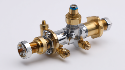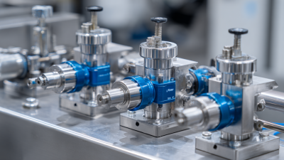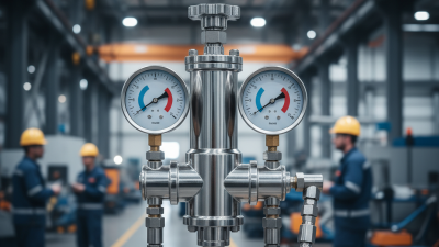
An equilibar back pressure regulator is more than a valve placed in a process line. It is a precision pressure-control device designed to maintain stable upstream pressure, even when flow conditions change. Unlike many conventional spring-loaded regulators, it uses a flexible diaphragm and a controlled reference pressure. This design can respond smoothly to very small pressure differences.
Jeff Jennings, Equilibar’s founder and president, describes the operating idea clearly: “The regulator responds to pressure, not flow.” That principle matters in laboratory systems, chemical processing, vacuum applications, and sensitive gas-handling equipment. A technician may watch the gauge needle remain steady while the downstream flow rises and falls. That quiet movement reflects careful control.
The term sounds simple.
In practice, sizing requires attention. Media compatibility, temperature, inlet pressure, outlet pressure, and expected flow must all be checked. A regulator that performs well with clean nitrogen may behave differently with corrosive vapor or liquid mixtures. Installation details matter too. Tubing volume, sensing-line arrangement, and pressure-source stability can influence real-world performance.
This guide explains what an equilibar back pressure regulator is, how its diaphragm-based design works, and where it can provide an advantage. It also considers practical limits. No regulator solves every pressure problem. That is an important point, and it is easy to overlook when product descriptions sound perfect. Reliable selection begins with measured process conditions, manufacturer data, and experienced engineering judgment.
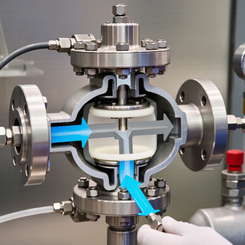
A back pressure regulator is a control device installed upstream of a process line. It maintains a chosen inlet pressure by adjusting flow through an internal diaphragm or valve. Unlike a pressure-reducing regulator, it does not mainly protect the equipment after the regulator. It protects the pressure conditions before it.
Back pressure matters because many processes depend on stable pressure. In a laboratory reactor, unstable pressure can change reaction rates, gas dissolution, or liquid boiling behavior. In a filtration system, excessive pressure may damage the membrane. A properly adjusted regulator keeps the process closer to its intended operating range. Small pressure changes can matter.
In practical testing, technicians often watch two calibrated gauges: one before the regulator and one after it. They also check tubing size, fluid temperature, flow rate, and material compatibility. A setpoint is not magic. Response may change when flow pulses, viscosity shifts, or gas compressibility becomes significant. I have found that a regulator can appear stable during slow testing, then respond differently during rapid process changes. That is why commissioning should include realistic flow conditions, leak checks, and repeated pressure readings. The safest setting is based on measured behavior, not assumption.
What Is an Equilibar Back Pressure Regulator?
An Equilibar back pressure regulator maintains an upstream pressure by balancing dome pressure against diaphragm force. The process stream enters the inlet and pushes against a flexible diaphragm. A controlled gas pressure fills the dome above it. When dome pressure rises, the diaphragm moves toward the seat, restricting flow. When upstream pressure falls, the diaphragm lifts and allows more flow. The response is continuous, not a simple on-off action. It feels like a firm hand adjusting a valve as pressure changes.
The upstream setpoint depends on the force balance: process pressure multiplied by diaphragm area must match dome pressure and opposing mechanical forces. A larger diaphragm can create greater control sensitivity at low flow. Field technicians should verify this relationship with calibrated gauges, stable gas supply, and slow setpoint adjustments. Small tubing leaks can distort readings. They are easy to overlook.
The U.S. Department of Energy’s 2022 Industrial Decarbonization Roadmap reports that process heating represents about 51% of manufacturing energy use. Stable back pressure can support tighter combustion and process control in those systems. The 2023 International Energy Agency energy efficiency analysis also emphasizes measurement and control as practical efficiency tools. Still, published figures do not replace site testing. Temperature, gas compressibility, pulsation, and diaphragm wear can shift the real operating point. A regulator may appear accurate on a bench, yet behave differently beside a pump or reactor.
| Data Dimension | Representative Value or Relation | Operating Principle | Engineering Significance |
|---|---|---|---|
| Regulator function | Controls upstream pressure | A back pressure regulator modulates its flow opening to maintain the desired pressure on the inlet side. | The controlled variable is upstream pressure, not downstream pressure. |
| Pressure-sensing element | Flexible diaphragm | The diaphragm responds to the pressure difference between the process side and the dome or control side. | Diaphragm movement changes the restriction between the inlet and outlet. |
| Dome pressure | 2.0 bar(g) in the example | Pressure applied to the dome produces a force on the diaphragm and provides the primary control reference. | Increasing dome pressure generally increases the upstream pressure setpoint in a dome-loaded design. |
| Upstream pressure setpoint | Approximately 2.8 bar(g) in the example | The regulator seeks an equilibrium where the process-side force, dome-side force, and valve reaction forces are balanced. | The actual setpoint depends on diaphragm area, trim geometry, flow, temperature, and pressure losses. |
| Downstream pressure | 1.0 bar(g) in the example | Fluid exits through the controlled opening after the inlet pressure reaches the regulated value. | Downstream pressure must remain within the regulator's allowable operating range. |
| Effective diaphragm area | 10 cm² in the example | The effective area converts a pressure differential into a diaphragm force. | A larger effective area produces more force for the same pressure differential. |
| Illustrative pressure differential | 0.8 bar = 80,000 Pa | Calculated as upstream pressure minus dome pressure: 2.8 − 2.0 = 0.8 bar. | This simplified differential is used to demonstrate the force relationship. |
| Illustrative diaphragm force | Approximately 8 N | Using F = ΔP × A: 80,000 Pa × 0.001 m² = 80 N. For a 1 cm² effective area, the force would be 8 N. | Force calculations must use the actual effective area and all relevant pressure surfaces. |
| Flow below setpoint | Regulator tends to open | If upstream pressure falls below the setpoint, the force balance shifts and the diaphragm moves to increase the flow area. | The increased flow helps restore upstream pressure when sufficient supply is available. |
| Flow above setpoint | Regulator tends to close | If upstream pressure rises above the setpoint, the diaphragm moves in the opposite direction and reduces the flow opening. | Restricting flow prevents excessive upstream pressure when operating conditions permit control. |
| Control mode | Pressure-balanced modulation | The valve does not simply switch fully open or fully closed; it continuously adjusts position in response to pressure changes. | Modulation can provide stable pressure control over a changing flow range. |
| Gas and liquid service | Application-dependent | The same force-balance concept can be used with gases or liquids, but sizing must account for compressibility, viscosity, density, and phase behavior. | Correct sizing is essential to avoid instability, excessive pressure drop, or inadequate capacity. |
| Setpoint adjustment | Usually adjusted by dome pressure | A controlled pressure source can be used to raise or lower the diaphragm loading force. | The adjustment method should match the regulator design and the required control accuracy. |
| Key design limitation | Not a substitute for a relief device | A back pressure regulator controls normal operating pressure but may not protect equipment during every failure condition. | A properly selected independent relief or overpressure protection system may still be required. |
Note: Numerical values in the force example are illustrative engineering calculations rather than product specifications. Actual performance depends on the regulator geometry, diaphragm effective area, fluid properties, temperature, flow rate, and installation conditions.
A back-pressure regulator maintains upstream pressure by opening when process pressure rises. The 0.1–2,500 psig span does not describe one universal setting. It represents multiple model-specific pressure ranges. Selection should match the actual inlet pressure, outlet pressure, and expected pressure variation.
Cv indicates the regulator’s flow capacity. A higher Cv can reduce restriction, but it may respond less smoothly at low flow. ISA-75.01.01 sizing practice links Cv with flow, pressure drop, specific gravity, and compressibility. ΔP matters too. A regulator may tolerate high upstream pressure while requiring a minimum differential pressure for stable control. These values should come from the individual datasheet, not a range chart alone.
Temperature limits deserve equal attention. Process heat can affect seals, sensing elements, and material strength. API 520 guidance is useful when pressure protection interacts with the control system, although it does not replace the regulator manufacturer’s limits. In field commissioning, engineers often discover that a cold-start condition changes viscosity and flow. That detail is easy to miss.
Tips: Record normal, minimum, and maximum pressure. Check Cv at the real flow rate. Confirm temperature during startup, cleaning, and shutdown. Do not assume the widest 0.1–2,500 psig range offers the best control. It may not. A smaller, correctly matched range is often more stable.
Reference pressure span for model-specific regulators: 0.1–2,500 psig
A back pressure regulator maintains a controlled upstream pressure by relieving excess flow. The logarithmic chart shows representative pressure reference points across the stated 0.1–2,500 psig span. Cv, allowable ΔP, and temperature limits are model-specific specifications and should be verified against the applicable technical datasheet.
A back pressure regulator maintains upstream pressure by adjusting outlet flow. It opens when inlet pressure exceeds the chosen setpoint. This action protects pumps, reactors, filters, and sensitive test equipment. Correct sizing prevents unstable control, excessive pressure loss, and unnecessary wear.
For sizing, apply the ISA-75.01.01 and IEC 60534-2-1 Cv equations. These standards relate flow rate, pressure drop, fluid density, temperature, and valve capacity. For liquids, calculate Cv from flow, specific gravity, and pressure difference. For gases, include absolute upstream pressure, temperature, compressibility, and expansion effects. Check whether the flow becomes choked. In that condition, increasing downstream pressure may not increase flow. Small calculation errors matter. A missing absolute-pressure conversion can produce an unsafe result.
Tips: Collect real operating data before selecting Cv. Record minimum, normal, and maximum flow rates. Measure inlet pressure at the regulator connection, not several meters away. Include startup conditions and possible pressure surges. Select a regulator that controls near its effective operating range, rather than barely passing the maximum flow. Oversizing often causes hunting at low demand. Undersizing creates a stubborn pressure rise. I have seen calculations appear correct until gas temperature changed during a test. Recheck the result with actual fluid properties and, when possible, a qualified engineer.
An equilibar back pressure regulator maintains upstream pressure by opening when process force exceeds the set point. Unlike a simple shutoff valve, it responds continuously to changing flow. Gas service demands stable control during compression, blending, and sampling. Liquid service requires attention to viscosity, pulsation, and cavitation. Small tubing can behave badly.
The IEA’s Global Methane Tracker 2024 estimates that fossil-fuel operations released about 120 million tonnes of methane in 2023. Reliable pressure control can reduce venting during transfer and testing, although it cannot replace leak detection. For vacuum systems, the regulator must prevent excessive negative pressure and protect fragile vessels. Relief duty needs independent sizing against credible blocked-outlet, fire, and thermal-expansion cases. ISO 4126 and API 520 remain useful references, but field conditions still decide performance.
A 4–20 mA control signal allows remote adjustment from a control system. The live-zero design helps distinguish zero output from a broken wire. Installers should verify sensor range, fail position, response time, and signal isolation before commissioning. In practice, “set pressure” is not always stable. Temperature, upstream volume, and diaphragm wear can shift it. I would record pressure traces at normal and upset flows, not trust one bench reading. EIA’s Annual Energy Review shows industrial energy use remains substantial, making efficient control relevant beyond laboratory accuracy. Safety still comes from tested relief protection, correct materials, and documented maintenance.