


Top Hydraulic Flow Control Valve Manufacturers in 2026
A hydraulic flow control valve can decide whether a press moves smoothly or a cylinder jerks under load. Its small passages and finely machined spool affect speed, heat, and repeatability. For buyers, choosing a manufacturer is therefore a practical engineering decision, not just a price comparison.
The U.S. Department of Energy’s Improving Pumping System Performance sourcebook reports that pumping systems can account for 25–50% of electricity use in some industrial facilities. That figure covers pumping systems, not valves alone, but it shows why controlling flow and avoiding wasted energy matter. NFPA’s fluid power industry data also tracks shipment trends across the sector, offering useful context for demand and product availability. Market estimates vary. Their categories do not always match.
This 2026 guide compares leading manufacturers through details that matter on the factory floor: pressure and flow ratings, adjustment range, response stability, materials, service access, and documented testing. A valve that performs well on a clean test bench may behave differently with hot oil, contamination, or frequent load changes. That detail is easy to overlook. Manufacturer reputation matters, but it cannot replace checking specifications against the actual circuit. The strongest choice may be less familiar, or less expensive. It deserves the same scrutiny.
Hydraulic Flow Control Valves: Purpose and Main Functions
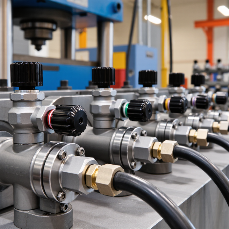
A hydraulic flow control valve meters oil moving through a circuit, shaping actuator speed rather than directly setting its force. A smaller opening usually restricts flow and slows a cylinder or motor. The relationship is not perfectly simple: pressure, oil viscosity, and load can change the result. Heat matters.
Valve selection starts with the required flow range and operating pressure. Engineers also check pressure drop, temperature limits, contamination tolerance, and whether the valve needs one-way flow. On a machine, a poorly matched valve may make a cylinder creep, respond unevenly, or waste energy as heat. Small details show up fast.
Energy use deserves attention. The U.S. Department of Energy’s Improving Pumping System Performance: A Sourcebook for Industry reports that pumping systems can account for 25%–50% of energy use in some industrial plant operations. That figure covers pumping systems broadly, not hydraulic valves alone, but it highlights why avoidable restriction matters. A flow-control valve cannot fix an oversized pump or poor circuit layout by itself. It can, however, help deliver the flow an actuator actually needs. Measure flow and pressure under working conditions; catalogue values alone can mislead. I would still recheck the setup after oil temperature stabilizes. Real machines rarely stay textbook-clean.
Top Hydraulic Flow Control Valve Manufacturers in 2026 - Hydraulic Flow Control Valves: Purpose and Main Functions
Technical comparison of common hydraulic flow-control valve designs and the functions to consider when evaluating a manufacturer’s product range. Applications and performance depend on the specific valve design and system conditions.
| Valve type | Purpose and main function | How flow is controlled | Common applications | Key selection considerations |
|---|---|---|---|---|
| Fixed-orifice flow control valve | Restricts flow through a fixed opening to limit actuator speed. | Flow changes with the pressure difference across the orifice and the fluid’s properties; the opening is not adjusted during operation. | Simple circuits where a basic, relatively steady restriction is acceptable. | Orifice size, expected pressure drop, fluid cleanliness, and whether changing load pressure will cause an unacceptable speed change. |
| Adjustable throttle or needle valve | Allows manual adjustment of flow to set or tune actuator speed. | A hand-operated element varies the passage opening. Without pressure compensation, flow generally varies as the pressure drop changes. | Low-complexity circuits, setup adjustments, and applications where load-related speed variation is acceptable. | Adjustment range, repeatability, pressure and flow ratings, vibration resistance, and the need for a check valve for reverse free flow. |
| Pressure-compensated flow control valve | Maintains a more consistent set flow despite changes in load pressure, within the valve’s compensation range. | A compensator adjusts the metering pressure drop so the flow-setting element receives a more stable differential pressure. | Actuator-speed control where load changes would otherwise cause significant speed variation. | Rated flow, minimum operating pressure differential, compensation range, pressure rating, and heat generated by throttling. |
| Pressure- and temperature-compensated flow control valve | Helps maintain a set flow when both pressure conditions and fluid temperature vary. | Pressure compensation stabilizes the metering differential; a temperature-compensating feature helps account for viscosity changes. | Systems that experience substantial operating-temperature variation and require more consistent flow. | Specified compensation limits, fluid viscosity range, rated pressure and flow, and the operating temperature range. |
| One-way flow control valve | Controls flow in one direction while permitting relatively unrestricted flow in the opposite direction. | A throttle meters flow in the controlled direction; an integrated check valve provides a bypass path for reverse flow. | Meter-in or meter-out actuator circuits, including applications requiring faster return travel. | Correct flow-control direction, check-valve cracking pressure, metering configuration, and suitability for the actuator and load. |
| Flow divider / combiner valve | Divides inlet flow between branches or combines flows from separate branches; some designs help synchronize actuators. | Internal elements allocate or combine flow according to the valve design. Flow division does not necessarily guarantee identical actuator movement under every load condition. | Multi-actuator circuits, paired cylinders, and hydraulic circuits that need controlled branch-flow distribution. | Division ratio, total and branch flow ratings, allowable pressure differential, leakage, and required synchronization accuracy. |
| Priority flow control valve | Supplies a designated priority circuit before directing surplus flow to a secondary circuit. | A regulating element maintains priority flow when supply conditions permit; remaining flow is directed to the excess-flow port. | Circuits that must preserve flow to a steering or other designated priority function while serving auxiliary loads. | Priority-flow setting, inlet-flow capacity, pressure rating, port arrangement, and behavior when inlet flow is insufficient. |
| Proportional flow control valve | Provides electrically commanded, variable flow for controlled actuator speed. | An electrical input positions a proportional metering element. Actual flow also depends on valve design and circuit pressure conditions. | Automated machinery and systems requiring adjustable or remotely commanded motion. | Command signal, flow curve, response characteristics, pressure compensation requirements, electrical protection, and control-system compatibility. |
Related Posts
-
How to Choose a Hydraulic Flow Control Valve
-

2025 How to Choose the Right Temperature Control Valve for Your Needs
-
Leading the Global Market with China's Best Gas Pressure Regulator Innovations
-
Understanding Pressure Regulators for Optimal Performance in Industrial Applications
-
Top 10 Back Pressure Valves Every Global Buyer Should Know?
-
Top 10 Flow Control Valve Types and Their Applications?