What Are the Top Types of Control Valves?
Control valves regulate flow, pressure, temperature, and liquid level across demanding process systems. Their choice affects product quality, energy use, equipment life, and safe operation. As the Fisher Control Valve Handbook defines it, “A control valve is a power-operated device that modifies the fluid flow rate in a process control system.” Process-control authority Béla G. Lipták has also written extensively about how measurement, control, and final elements work together. That system-level view matters: a valve cannot compensate for poor instrumentation or an unsuitable process design.
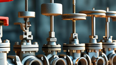
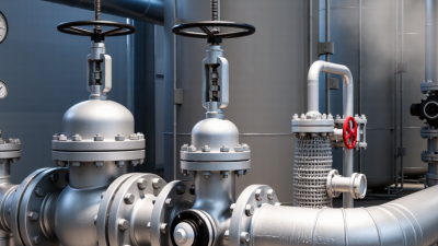
This overview compares the main control valve types, including globe, butterfly, ball, plug, diaphragm, and pinch valves. Each design has trade-offs. A globe valve may offer precise throttling, while a butterfly valve can suit larger pipes where compactness matters. Ball valves often provide strong shutoff, but not every design handles continuous throttling equally well. Diaphragm and pinch valves can help isolate corrosive or particle-laden fluids, depending on materials and operating conditions.
Details matter. Consider a sticky slurry, a narrow pressure range, or a pipe vibrating beside a pump. The “best” valve changes with the service. Engineers typically assess flow characteristics, pressure drop, temperature, fluid compatibility, noise, maintenance access, and actuator needs before selection. Manufacturer data and field experience should both inform the decision. Even then, uncertainty remains; real service conditions can differ from design assumptions. This guide offers a practical starting point, not a substitute for application-specific engineering review.
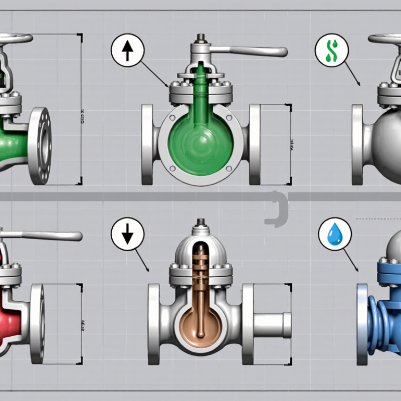
What Is a Control Valve and What Role Does It Serve?
A control valve is the adjustable device in a process control loop. It changes the flow of a liquid, gas, or steam in response to a controller’s signal. An actuator moves the valve; a positioner can help it reach the requested opening. That movement influences process variables such as pressure, temperature, level, and flow. Small changes matter. For example, throttling a steam line can help stabilize equipment temperature, while a valve on a tank inlet can regulate its filling rate. The valve does not make decisions on its own. It responds to the control system and operating conditions.
The International Energy Agency’s 2023 Energy Efficiency report estimates that industry uses about 37% of global final energy. That figure is broader than valve performance, but it shows why careful process control matters. A correctly selected valve can help maintain stable operation and reduce avoidable flow or pressure fluctuations. Selection still depends on fluid properties, pressure drop, required flow range, and failure position. A valve is not a cure-all. Poor sizing may cause noise, vibration, or unstable control, and real operating conditions can be messier than design calculations suggest.
Tip: Check the valve’s sizing and operating range against actual process data, not just pipe diameter. Review cavitation, erosion, and shutoff needs with a qualified controls or process engineer.
What Are the Top Types of Control Valves?
How common flow characteristics affect a control valve’s response as it opens.
What the chart shows: A control valve regulates fluid flow by changing the size of its opening in response to a control signal. Linear valves increase flow roughly in proportion to valve travel; equal-percentage valves produce progressively larger flow changes at higher openings; quick-opening valves deliver much of their flow early in the opening stroke. These are idealized inherent characteristics at constant pressure drop, not measured performance data. The equal-percentage curve uses an illustrative rangeability of 50:1; actual behavior depends on valve design and operating conditions.
How Are Control Valves Classified by Motion and Flow Path?
Control valves are commonly classified by the movement of their closure element and the route fluid takes through the valve body.
These categories describe different features: motion explains how the valve opens, while flow path shows where the fluid goes. Linear-motion valves, such as globe and diaphragm types, move a plug or diaphragm along a straight axis. Rotary valves, including ball, butterfly, and plug types, turn a disc or shaped element, often through a quarter turn.
Not always neat.
Some designs overlap in application, so a valve’s category alone does not indicate its control precision or maintenance needs.
Flow-path classification focuses on the body’s internal passages.
A straight-through design sends fluid along a relatively direct route, while an angle-body design redirects it through a turn. Multiport valves can connect several passages, allowing a system to divert or mix streams. Picture a pipe layout with one inlet and two outlets: a multiport valve may send flow to either branch, depending on its configuration. Pressure loss, available space, and the fluid’s properties all affect which route makes sense.
Tips:
Check the piping diagram and valve data sheet together. Confirm port arrangement, flow direction, and operating motion before installation. A small mismatch can disrupt flow. Also consider how the valve will be inspected; real layouts are sometimes less tidy than drawings suggest.
What Are the Main Linear-Motion Control Valve Types?
What Are the Main Linear-Motion Control Valve Types?
Linear-motion valves move a stem or flexible element along a straight path to regulate flow. Globe valves are common in modulating service because their plug moves gradually toward or away from a seat. This allows relatively precise adjustment, though pressure loss can be higher than with some other designs. Diaphragm valves use a flexible membrane to control flow and keep process fluid away from moving stem components. They can suit corrosive fluids, but diaphragm material and operating limits need careful review. Pinch valves squeeze a sleeve closed, making them useful for slurries with suspended solids. Gate valves also move linearly, but they are generally better for on-off duty than frequent throttling. Simple, but important.
Tips: Match the valve to the fluid, pressure, temperature, and required control range. Check for abrasive particles, too. A sleeve or diaphragm can wear sooner than expected in demanding service. I still find that real operating conditions are less tidy than a selection chart suggests.
Before choosing, compare actuator force, leakage needs, maintenance access, and available space. A globe valve may offer finer control, while a pinch design may handle solids more gently. Confirm the expected flow range with process data, not pipe size alone. That small check can prevent unstable control later.
What Are the Top Types of Control Valves? – What Are the Main Linear-Motion Control Valve Types?
| Valve Type |
How It Controls Flow |
Typical Uses |
Key Advantages |
Important Considerations |
| Single-Seat Globe |
A linear-moving plug approaches or withdraws from one seat to regulate the flow opening. |
General-purpose liquid, gas, and steam control where accurate throttling and relatively tight shutoff are required. |
Good controllability; a single seat can provide tighter shutoff than many double-seat designs. |
Pressure forces on the plug can require substantial actuator thrust, especially at higher pressure drops or larger sizes. |
| Double-Seat Globe |
A moving plug controls flow through two seats at the same time. |
Applications with larger flow capacity where reduced net fluid force on the plug is useful. |
Opposing pressure forces can reduce the actuator thrust needed compared with a similar unbalanced design. |
Achieving tight shutoff is more difficult because both seats must seal; leakage may be greater than in a single-seat design. |
| Cage-Guided Globe |
A plug moves linearly within a perforated cage that guides the plug and shapes the flow passages. |
Process control requiring stable plug guidance, interchangeable trim options, or noise and cavitation management. |
Trim can be configured for different flow capacities and characteristics; the cage provides robust plug guidance. |
Performance depends on selecting trim suited to the fluid, pressure drop, and operating conditions; small passages can be sensitive to solids. |
| Angle-Pattern Globe |
A linear-moving plug regulates flow through a body with an inlet and outlet arranged at an angle, commonly 90 degrees. |
High-pressure-drop services, flashing or erosive flow, and piping layouts that benefit from a change in flow direction. |
The body can simplify piping at a turn, and suitable designs can help manage erosive or flashing service. |
Body and trim selection must account for fluid velocity, erosion risk, and the direction of flow. |
| Three-Way Globe |
A linear-moving plug routes flow between three ports for mixing two streams or diverting one stream. |
Temperature-control loops, blending duties, and systems that need to mix or split process flows. |
Combines mixing or diverting action in one valve body. |
Mixing and diverting configurations are not interchangeable; port arrangement and flow direction must match the application. |
| Diaphragm Control Valve |
An actuator moves a flexible diaphragm against a weir or seat to vary the flow passage. |
Corrosive, viscous, or solids-bearing fluids, and services where isolating the process fluid from the stem is beneficial. |
The diaphragm can separate the process fluid from the operating mechanism; weir-style bodies can handle some suspended solids. |
Diaphragm material and temperature limits matter; pressure and temperature capabilities are generally more limited than those of many metal globe valves. |
| Pinch Valve |
A linear actuator compresses a flexible sleeve to restrict or stop flow. |
Slurries, powders, and fluids containing suspended solids where minimizing internal obstructions is important. |
The sleeve provides a clear flow path when open and can isolate the fluid from most valve-body components. |
The sleeve is a wear component; its material and service life depend on fluid compatibility, pressure, temperature, and cycling. |
What Are the Main Rotary-Motion Control Valve Types?
Rotary-motion control valves regulate flow by turning a closure element, often through a quarter turn. Butterfly valves use a disc inside the pipe. They are compact and light, making them useful on large water or air lines. However, the disc remains in the flow path, so it can create pressure loss even when fully open.
That detail is easy to overlook.
Ball valves rotate a drilled ball to change the flow area. Segmented-ball designs, including V-shaped openings, can provide more precise throttling than standard on-off balls.
Plug valves use a rotating plug with a shaped port; eccentric plug designs can handle some dirty or abrasive services because the plug moves away from the seat as it opens.
Each type behaves differently as it travels, so actuator sizing and control stability matter. Small details count.
Selection depends on fluid, pressure, temperature, leakage needs, and the required flow range. A butterfly valve may suit a large, low-pressure line, while a segmented ball valve may offer better control for changing loads. Check the manufacturer’s flow curves and materials data against actual operating conditions. A tidy comparison table can help, but it cannot capture every installation. I would still verify the expected range with a qualified valve engineer.
How Do You Match a Control Valve Type to Its Application?
Start with the process conditions, not a valve’s popularity.
Record the fluid, operating temperature, pressure drop, flow range, and required shutoff. A valve that handles clean water may behave poorly with hot, abrasive slurry. Check the required flow coefficient, or Cv, at normal and peak demand. Also consider actuator response and what the valve should do if power or air fails.
Globe valves offer stable throttling for many changing-flow duties, though they can create a larger pressure drop.
Ball valves suit high-capacity service and quick shutoff; a characterized port can improve control.
Butterfly valves are compact for larger lines, but standard designs may struggle with precise throttling near closed positions. For corrosive fluids or suspended solids, diaphragm or pinch valves may be worth evaluating. Material compatibility matters. So does maintenance access. There is no perfect choice, and a sizing calculation can still miss real operating patterns. Review the selection against actual process data.
Tips: Ask operators about startup, cleaning, and common flow changes. Compare the valve’s rangeability with the process range, and verify fail position with the safety design. If readings are uncertain, get better measurements before final sizing.